 |
| This is the second article in a series. Click here for the series index. |
To sum up: now is the time to try things out, reject what you don't like, keep what you do, and most importantly keep tweaking until you get things just right.
Concepts
Before we get started, there are some things to bear in mind when creating our world map. First and foremost, the world map is necessarily an extremely small scale map. Consequently, it cannot show your world in very high detail; nor does it need to. In many respects, world maps are vague and inaccurate. They simply lack the kind of resolution needed to display high levels of detail. In layman's terms, they are just too far zoomed out to see much more than general shapes.
What this means is that your world map is your base map, upon which all other maps are based, but regional and local maps do not have to reflect it 100%. On the contrary, they should develop and expand upon the foundations contained in the world map, introducing new details too fine to show up on it, as well as revising and enhancing those details that did appear on the world map.
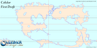 |
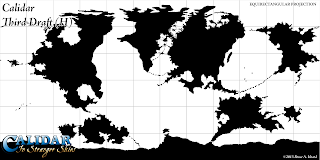
+Bruce Heard's very first design for Calidar's world map. Note
how the Great Caldera is already present, but joined up with the
adjacent continents. This map was drawn directly onto a 2:1
Equirectangular Projection using Paint.NET. The resolution
was 6000 x 3000.
|
If you deem it necessary, the world map can be rebuilt later to reflect the more detailed regional maps, but this should be considered strictly optional. There is probably not a lot to be gained by doing so, as the lower resolution of the world map will obscure the added details anyway. In general, world maps should remain reasonably simple and unburdened with tiny details, to fulfil their main purpose as overview maps.
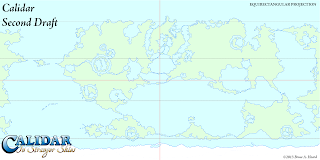 |
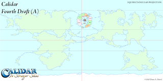
| Bruce's second draft incorporated impact craters throughout the world, so that there were numerous areas like the Great Caldera. It also split the Great Caldera from its neighbouring continents. |
The reason for this is that at this stage, only the general shapes are important; small details on the coasts can be added later, so there's no need to worry about things looking too regular.
It's worth noting here briefly the differences between raster and vector art. Raster graphics, also known as bitmaps, are comprised of arrays of tiny dots known as pixels. Most people are familiar with these images from photographs, paint programs, and indeed the Internet. Common formats are PNG, JPG, and GIF. Photoshop and most other paint programs mostly work with raster images. Raster images can often be shrunk down without incurring great problems, but enlarging them causes them to become blocky and/or blurry, and is best avoided. This means that you need to consider what resolution to work in from the start, because you won't be able to increase it later on.
Vector graphics, in contrast, are made up of mathematical descriptions of lines and points. They don't use pixels at all, although they can be rasterised – i.e. changed into pixel arrays. Because they are defined using lines and points, it's possible to resize them freely without losing sharpness. Fonts are probably the most common vector graphics encountered in daily life. Illustrator works primarily with vector graphics. Vector formats include SVG, DXG, AI, and many others.
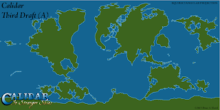 |
| I took a stab at the third draft, tracing Bruce's outlines to Illustrator vectors. I went back to the first draft and tried to split things up to look more earth like. |
It's worth noting here briefly the differences between raster and vector art. Raster graphics, also known as bitmaps, are comprised of arrays of tiny dots known as pixels. Most people are familiar with these images from photographs, paint programs, and indeed the Internet. Common formats are PNG, JPG, and GIF. Photoshop and most other paint programs mostly work with raster images. Raster images can often be shrunk down without incurring great problems, but enlarging them causes them to become blocky and/or blurry, and is best avoided. This means that you need to consider what resolution to work in from the start, because you won't be able to increase it later on.
Vector graphics, in contrast, are made up of mathematical descriptions of lines and points. They don't use pixels at all, although they can be rasterised – i.e. changed into pixel arrays. Because they are defined using lines and points, it's possible to resize them freely without losing sharpness. Fonts are probably the most common vector graphics encountered in daily life. Illustrator works primarily with vector graphics. Vector formats include SVG, DXG, AI, and many others.
In Calidar’s case, Bruce worked with PNG raster images in Paint.NET. I then auto-traced those images in Illustrator, turning them into vectors, before making adjustments and exporting to PNG to send back to Bruce. I prefer vectors for coastlines, but lately I have been using high resolution raster PNG files more and more, because it's easier to roughen coastlines on a raster image.
Images in this section are courtesy of USGS. Check their Map Projections Poster for a full description of all the concepts in this section.
Planets are three dimensional objects: spheres, or more accurately ellipsoids. Maps, on the other hand, are flat two dimensional representations. When you make a two dimensional representation of a three dimensional planet, distortion of some kind is unavoidable.
 |
| Miller Cylindrical |
 |
| Lambert Conformal Conic |
 |
| Stereographic (Azimuthal) |
Properties that can be preserved include:
• Shape
• Area
• Distance
• Direction
• Bearing
• Scale
Of these, shape, area and distance are probably the most important, and projections that preserve them are the most well-known and widely used.
Projections preserving shape are known as Conformal Projections. Examples include Mercator, Stereographic, and Lambert Conformal Conic.
Those which preserve area are called Equal Area Projections. Examples include Gall-Peters, Albers Equal Area, Lambert Azimuthal Equal Area, as well as Mollweide and Hammer.
 |
| Sinusoidal |
 |
| Robinson |
 |
| Normal Aspect Mercator |
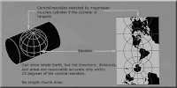 |
| Transverse Aspect Mercator |
 |
| Oblique Aspect Mercator |
Further reading on projections:
• Map projections at Wikipedia
• Map Projections Poster at USGS
• How to choose a projection at Hunter College (highly recommended!)
• G.Projector User's Guide: Projection List
Advantages of Projections
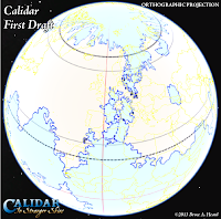 |
| Bruce's original world map design as an image overlay in Google Earth |
With that said, there are quite a few advantages to using projections in your maps, should you wish to do so. For example, you will be able to:
• Take advantage of reprojection techniques to design good-looking polar areas, avoiding distortion and spikiness.
• Produce multiple versions of your world map, choosing a projection to match the theme of each.
 |
| Icosahedral net made in Fractal Terrains using an Equirectangular height map |
• Take advantage of the properties of each projection in your maps.
• Place your map on a 3D model such as Google Earth.
• Create icosahedral maps or interrupted (segmented) projection maps to make paper globes.
• Make animated spinning planets using Photoshop’s 3D, or a 3D rendering program such as Bryce.
• Render impressive orbital views and space scenes.
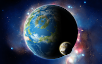 |
| Orbital view rendered in Photoshop using Equirectangular planet and moon maps |
For Calidar, we decided from the very start to work with projections. I had long wanted to do so with my work on Mystara, but was held back by the choices of Mystara’s original cartographers back in the 1980s. This is not a criticism - on the contrary, I have the utmost respect for all of the cartographers who worked for TSR, and they have undoubtedly influenced me more than anyone else. Of course, TSR's cartographers did not have access to the kinds of computers and software that we do today, so their job was that much harder.
Working with Projections
Before computers became so ubiquitous as they are today, cartographers were forced to make difficult calculations, or to use complex tables to convert maps from one projection to another. These days, however, there is freeware software to do this for us.
The most useful I have found is NASA’s G.Projector. There is also QGIS, but it’s much more complicated and harder to use.
If you want to take full advantage of projections, there are various commercial software options to choose from too. I use Manifold, which is one of the more affordable programs. I would love to be using Avenza Systems Inc.’s MAPublisher and Geographic Imager, which enable projection and other GIS functions directly within Illustrator and Photoshop respectively, but both are well out of my price range.
Whatever software you choose, you will need to learn how to load images into it, georeference them if necessary, change projections, and then export back to your usual image format.
Projections and the World Map
For various reasons, the best projection to work with for your world map is the Equirectangular Projection. Also known as Geographic Projection, Plate Carrée, or Latitude/Longitude Projection, it is nothing more than a simple grid of latitude and longitude. This inherent simplicity makes it a relatively easy projection to work with. But it’s important to know its strengths and shortcomings.
Equirectangular Projection
+ Simple grid of latitude by longitude, giving a 2:1 ratio image.
+ The required projection for Google Earth image overlays and texturing 3D models.
+ Up is always north, left is always west, etc.
+ Low north-south distortion of shapes.
+ North-south distances are accurate throughout the map.
- High east-west distortion of shapes, progressively increasing as you move away from the equator.
- Poles are stretched across the entire length of the map, making the polar regions difficult to work with.
- East-west distances are accurate only along the equator, and difficult to measure accurately elsewhere.
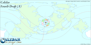
Google Earth image overlays showing the original designs for Calidar's north and south poles.
The results were somewhat less than stellar. Due to this distortion, we all but abandoned polar
landmasses in the second draft. It wasn't until the fourth draft that we tackled the problem,
with the help of G.Projector and the Oblique Equirectangular Projection.
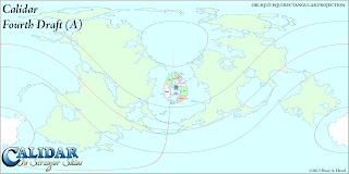
In terms of creating continental outlines, the main problem we have to deal with is the distortion of the polar areas. This is actually easy to solve, and you don’t even need to use a different projection to do so. Think about it for a moment: in an Equirectangular Projection, the equator area is relatively distortion-free. But why does the map have to be centred on the equator? In fact, it doesn’t. When you centre the map on a different parallel (or meridian!), it’s known as an Oblique Projection. What this means is that we can reproject the map to an Oblique Equirectangular Projection, so that the poles are relatively undistorted.
The same is true of any areas which need to be very specific shapes. For example, with Calidar, there are various impact craters around the world. All of these needed to be circular. It’s possible to do this simply by centring the Oblique Projection on the area of interest.
The important thing to bear in mind here is that the goal is to create a single base map. So everything that is done in a different projection must be reprojected back to the original projection, and then used as a guide to update the base map.
Using these techniques, it’s possible to build up a world which looks exactly as you want it to look.
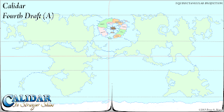 |
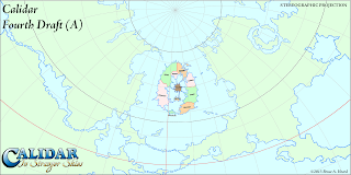
| I entered latitude -45º to reverse the change we made before, producing this map. As you can see, it's a little messy, so we used this as a guide to update the previous base map. |
You can now reproject the map in any way you like. G.Projector's list of projections is quite extensive. Experiment and see what each projection looks like.
For building the base map, the projection we're interested in is Equirectangular Oblique. Using the latitude and longitude controls, you can specify precisely where the map is centred. For example, the default is 45º. This centres the map on an oblique line beginning at 45ºN 0ºE, circling round to 45ºS. As a general rule, everything along the centre of the map (where the equator would be on a normal Equirectangular Projection) is free from distortion. So if you want to draw a specific shape of terrain at 60ºN 35ºW, you should centre the map there.
Setting the latitude to 90º centres the map on the prime meridian. You can choose a different meridian by changing the longitude setting. This is great for working on the polar areas. (Technically this is a Transverse Equirectangular Projection rather than an Oblique one, but the difference is purely terminology.)
Output maps centred on as many regions as you need, but be sure to note the settings used in the filename for each map. You'll need this information later to reproject the map back to the base Equirectangular map.
Now use whatever image editing program you like to edit your map, only changing the central area of each map.
Loading non-Equirectangular maps, or even Equirectangular maps centred on a location other than 0ºN 0ºE, is a little clunky. You will need to go into G.Projector's preferences and input the data there. After you have changed these settings, load in your map, and you should be able to put it back to the original projection.
The final step is to use your adjusted map to update your base map.
G.Projector is limited to images around 10,000 or less pixels long, so you can't work with super high resolution images.
Also note that leaving the graticule (the grid lines) turned on when exporting the map can be useful, but when loading the map back in the lines can become very confusing.
I'm sure this has been pretty confusing. Please give it a try for yourself, and see how it works. If you get stuck, post in the comments below and I will see if I can help you out.
Roughen outlines
So you have your world looking just as you want it. You've checked and rechecked using different projections. You've set it as an image overlay in Google Earth and navigated around your world as a globe.
Once you're sure that it's all done, the next stage is to roughen up the continental outlines. Mike Summers wrote a wonderful tutorial for this over at the Cartographer's Guild, or you can also see it on his blog. I don't want to steal Mike's thunder, so I will leave the details for you to discover there. I have used Mike's technique for all of Calidar's maps.
Once you're sure that it's all done, the next stage is to roughen up the continental outlines. Mike Summers wrote a wonderful tutorial for this over at the Cartographer's Guild, or you can also see it on his blog. I don't want to steal Mike's thunder, so I will leave the details for you to discover there. I have used Mike's technique for all of Calidar's maps.
I like to roughen again at each level of detail, so I do it first at world level, then again at regional/continental level (4 times the resolution), and finally once more at local level (another 4 times the resolution).
And that brings us to the end of the continental outlines section. If you managed to read this far, thanks! There is actually one topic which I left out: scale. I have decided that it deserves a post all of its own, so I will post it at a later date.
Please feel free to post any questions, comments, or corrections in the comments below.
Please feel free to post any questions, comments, or corrections in the comments below.


3 comments:
I'm a bit lost as to what to do after uploading the map. I can re download the map as an orthographic map but I can't figure out how to reupload it because the program thinks its been projected as an equirectangular map. There's no option to upload an orthographic map projection in the initial upload menu thing. pls help
Is there a way to force G.Projector to deliver higher resolution output than the 20000 x 10000 pixel limit, perhaps via command prompt?
I can get high resolution input by importing portions of a map, but I’m stuck at the export limitations.
Great insights! I never thought about it from this angle before. Thanks for broadening my perspective!
world map eu
Post a Comment